Expertise — 01
Engineering
Electrical systems and technical infrastructure, designed to be traced, measured and maintained.
01 / 03
Electrical Engineering
Distribution, protection, metering and control, laid out so that every circuit can be traced, measured and maintained.
- Electrical infrastructure
- Technical design & load analysis
- Distribution boards
- Lighting systems
-
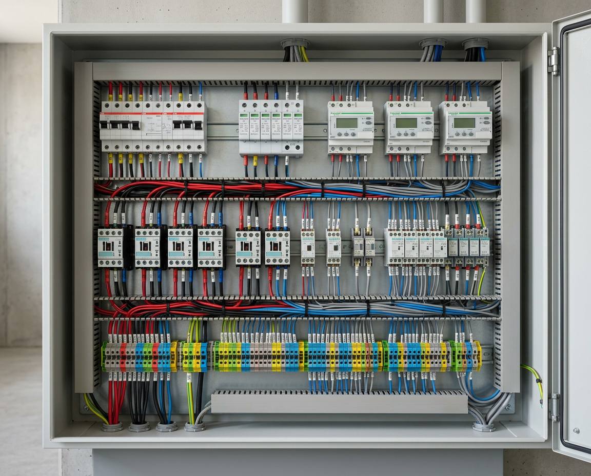
Circuit protection Miniature circuit breakers grouped and labelled by circuit.
-
Surge protection Surge protective devices on the incoming supply.
-
Energy metering Sub-meters that record consumption per line, ready for remote reading.
-
Load switching Contactors that switch heavier loads such as pumps, heaters and lighting groups.
-
Control relays Relays and timers that let automation act on the installation.
-
Terminal distribution Colour-coded terminal blocks, including protective earth, for outgoing circuits.
All capabilities
Electrical engineering
- Electrical infrastructure
- Technical design
- Load analysis
- Lighting
- Electrical projects
- Installation coordination
Project development
- Technical survey
- Project planning
- Renovation coordination
- Implementation management
- Commissioning
Engineering projects that require licensed approval and official signatures are carried out by authorized professionals in accordance with applicable regulations.
02 / 03
Precision is in the details.
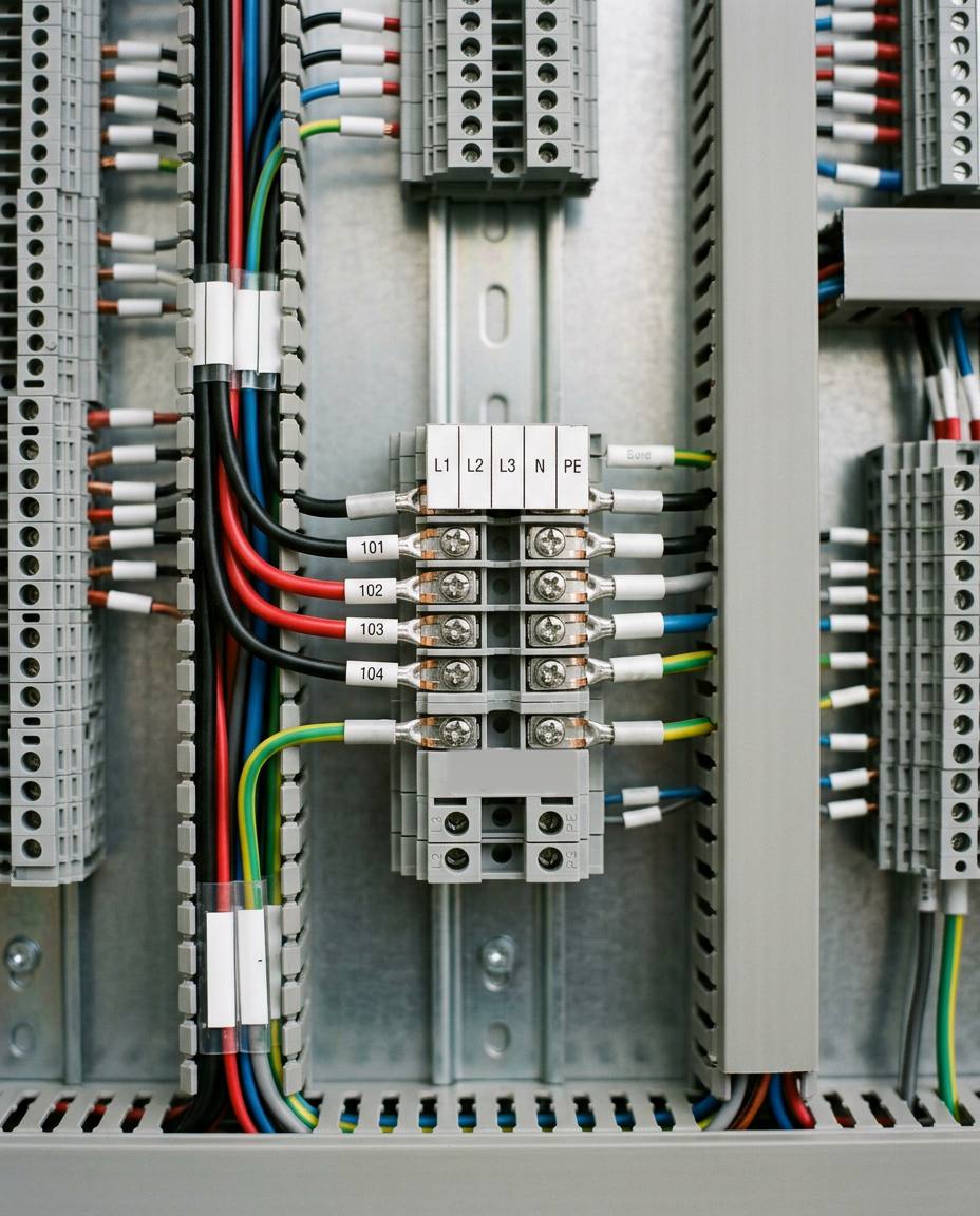
Labelled conductors, correct terminations and clean ducting are what make an installation safe to work on years later.
-
Three-phase distribution L1, L2, L3, neutral and protective earth, clearly marked.
-
Labelled conductors Every wire numbered and finished with a ferrule.
-
Cable ducting Slotted trunking that keeps runs separated and accessible.
-
Protective earth Green-yellow earth conductors routed to their own terminals.
03 / 03
Energy Monitoring
Consumption measured where it happens — per supply, per line, per system — and brought onto a screen you can read.
- Energy metering
- Consumption analysis
- Monitoring
- Reporting
-
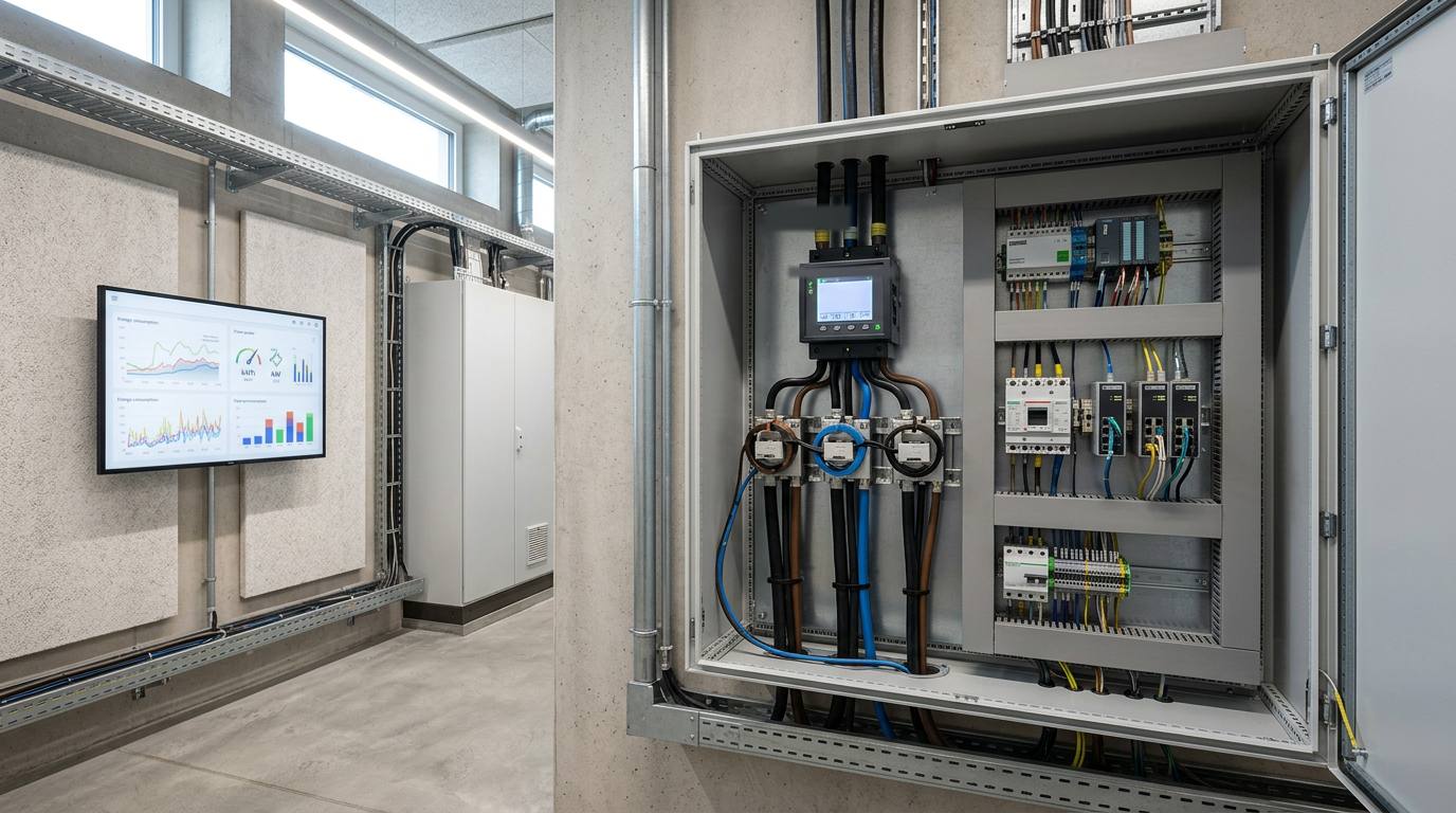
Multifunction power meter Voltage, current, power and energy on the incoming supply.
-
Current transformers One per phase on the incoming conductors, feeding the meter.
-
Communication & I/O Modules that bring meter and sensor readings onto the network.
-
DIN-rail switches Ethernet for meters, controllers and the monitoring screen.
-
Energy dashboard Consumption, demand and trends on one screen. Data on this screen is illustrative.
-
Cable containment Overhead trays that keep power and data runs apart.
All capabilities
Energy
- Energy metering
- Consumption analysis
- Monitoring
- Automation
Expertise
Expertise
-

-

Illustrative visuals